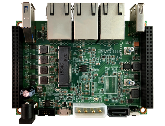
 The ESPRESSObin is a nice single-board computer with, unusually, 3 Ethernet ports and a SATA port. We have some plans for it (which I’ll talk about later) and which necessitated interacting with its GPIO pins.
But unfortunately, Globalscale’s documentation seems at odds with what the board actually does. So here are the results of some sleuthing, in the hope that it might be useful for somebody. No guarantees that I got it right, of course.
Software-side:
- To interact with the GPIO pins, go to directory
/sys/class/gpio. The Linux kernel maps them right into your (virtual) file system. - Each file
gpiochipXXXthat you find in that directory is a GPIO controller. The ESPRESSObin has two; mine are calledgpiochip446andgpiochip476. The actual values for XXX depend on the Linux distro and configuration that you run. The values in this post are from running the UBOS distro. - They control GPIO pins with indexes that start with (the content of file)
gpiochip446/basefor a total of (the content of file)gpiochip446/ngpioitems. Same for the other controller. - So apparently the first bank has 30, and the second 36 pins. Not all of them are connected, however, as we’ll see below.
- To get any of them ready for use, you need to “export” them. To do that, in that directory, you execute
echo NNN > export, where NNN is the pin number according to the above numbering scheme. For example,echo 503 > export. As a result, the Linux kernel will create a new (virtual) directory, such asgpio503which has (virtual) files in it that allow you to interact with that pin. (Actually it’s a symbolic link to the directory, but it won’t matter for this post). When you are done, you can “unexport” them the same way by sayingecho NNN > unexport. Neat, isn’t it? - Strangely enough, however, the entire ESPRESSObin hangs and needs to be rebooted if you “export” a whole bunch of those pins. Why I don’t know. Here’s what I found:
| 447-448 | works |
| 449-450 | hangs entire board |
| 451 | works |
| 452-463 | hangs entire board |
| 464-475 | works |
| 476-480 | error |
| 481-511 | works |
- I’m only interested in using them as outputs. In order to do that, after “export”ing a pin XXX, you set its direction by executing
echo out > gpioXXX/direction. This works for all pins that can be exported, except pins 509-511. They silently remain “in”. (Why I don’t know either. Perhaps the hardware does not support output functionality for them).
Hardware-side
- To figure out which hardware pins the map to on the two exposed headers, I used this highly sophisticated script. It switches all of them from High to Low and back with 1/2 Hz, so by connecting an LED I can easily see if I am connecting to a member of this set:
cd /sys/class/gpio
while true; do for f in */value; do echo 1 > $f; done; sleep 1; for f in */value; do echo 0 > $f; done; sleep 1; done
- After I narrowed down the candidates, I created myself a working list with
ls -1d gpio[45]* > /tmp/alland then flashed them one at a time:
while true; do for f in $(cat /tmp/all) ; do echo $f; echo 1 > $f/value; sleep 1; echo 0 > $f/value; done; done
- It goes faster if you remove any identified entries from
/tmp/all. - Here are the results:
| P9 Header | P8 Header | ||
|---|---|---|---|
| left column | right column | left column | right column |
|
20: 477 (default 1.8V) 24: 494 (default 1.8V) 26: 495 (default 1.8V) 28: 493 (default 1.8V) |
15: 484 (default 0.8V) 19: 476 (default 1.8V) 23: 485 (default 0.8V) 25: 486 (default 0.8V) 35: 481 (default 1.8V) 37: 482 (default 0.8V) 39: 483 (default 0.8V) 41: 491 (default 1.8V) |
6: 504 (default 1.8V) 20: 507 (default 1.8V) 22: 506 (default 1.8V) |
5: 503 (default 1.8V) 7: 492 (default 1.8V) 23: 505 (default 1.8V) |
So a total of 19 output pins are available and usable. Unfortunately, the pinout is completely different than what the ESPRESSObin documentation has. But well, at least now I have something that works for me!
Update 2017-12-04: removed duplicate pin 504 in table. Transcription error!
Update 2017-12-04: I added the default voltages of the pins upon boot without any configuration. Unfortunately most seem to be at 1.8V, with an internal resistance of about 10kOhm, instead of default high impedance. That makes it rather difficult for attached electronics to only operate once they have been configured as “OUT”.