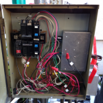
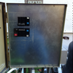
(Previously I discussed the the why of this project, the parts I selected to build with, setting up the Raspberry Pi itself, and the electronic assembly In this post, it’s getting serious: I put all the parts together in place in the back yard.)
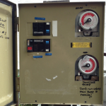 Recall that I got into this project because an old electromechanical timer had failed. The current control box has custom cut-outs for those timers, and it would not be safe to keep those holes there after the timers have been removed. So it’s time to look for a replacement.
This turns out to be a bit of a hit-or-miss game. The local hardware stores (Home Depot, Lowe’s, Orchard Supply) don’t sell any suitable boxes, nor suitable sheet metal, and do not do custom sheet metal cuts in any case. For some time, I only find metal-working shops in the area that don’t do odd lotsize-1 jobs. But then I happen to call Advantage Metal Products in Santa Clara, who take the old front panel, and one hour later, hand me a stainless-steel sheet the same size for a very reasonable price. I still need to cut out the holes for the circuit breakers myself, which, as expected, is a bunch of work involving drilling, jigsawing, and lots and lots of filing. The fact that sheet metal of this size does not really fit into my vise is not helping either. This part of the project draws blood and swearing. I even end up with a steel splinter from a filed edge, and I did not know one could get such a thing in the first place. Perhaps stainless steel behaves differently?
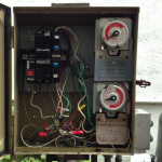
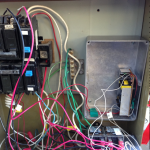
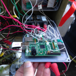
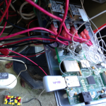
Time to rip out the old timers, and put it the new assembly which now has been placed into the metal box I bought earlier. I’ll let the pictures speak for themselves.
In the second picture, you can see the what’s left of the power supply whose enclosure I smashed. In the forth picture, the two transistors in the transistor stage driving the relays are clearly visible on the prototyping board between the Raspberry Pi board and the relays. Once the box is closed, the Wi-Pi dongle is inserted into the Raspberry Pi’s USB slot through a hole that I cut into the metal box. And finally, with the new front panel, absolutely nothing tells that something untowards is happening behind this steel wall :-) In the future extension, I am planning to put at least a simple button there that allows the user to toggle the current state of the pumps. But that’s a possible feature for the next version.
In terms of wiring, I have the relays switch both terminals of the pumps. The power is routed by way of the separate circuit breakers (one for each pump) that were there before. The project’s own power supply has its own circuit breaker with ground fault detector.
This is when things usually don’t work. You switch on the circuit breaker, and nothing happens. And so it is here. Turns out that the (previously unused, no idea why, what was the previous home owner up to again?) circuit breaker I chose for the project’s own power needs is faulty. A trip to Home Depot fixes this. (But not to Lowe’s, they say they don’t have circuit breakers with ground-fault detection. Huh?) Amazement occurs when the Raspberry Pi boots, the blue LED of the Wi-Pi comes on, DNS and DHCP and everything work, I enter http://pool/piStatus.pl into the iPad, standing next to the panel, and miracle over miracles, the pumps come on when I fiddle with the pin settings through piStatus.pl.
Actually I lied. It works fine when the panel is still open. Once I close it, the metal enclosures weaken the WiFi signal enough to break the connection. I was expecting that. So I add a USB extension chord, and move the Wi-Pi outside of the box at the bottom. Currently, it would get wet if it rains badly. But I have the plastic box to put it in to keep it out of the rain, and that’s the project for tomorrow.
So it works. Everybody in the family gets to play with it. Via piStatus.pl, no less, which is not exactly what a normal person would expect, in particular because I keep forgetting which I/O pins I used. Which is why I need software: Rasptimer is the subject of the next post.
