(See this post on the why of this project, this post on the parts I selected to build with, and this post on setting up the Raspberry Pi itself. In this post, I describe my travails assembling the electronics.)
I used to do many projects like this as a teenager, an eternity ago as it seems. One thing I learned the hard way is to always, always, assemble projects gradually, starting with the power. If the power is wrong, in the best case, you get really befuddled about what is going on, and in the worst case, you have to reorder every single part you just fried. (May include yourself ;-)) And reassemble everything while being angry. With the infernal stinkage of exploding electrolytic capacitors in between.
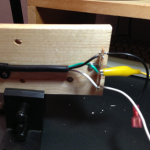
For this reason, I have this rather effective, but highly unorthodox “access to the power outlet” contraption. It’s basically an old power chord, with access to the wires, so I can quickly clip on whatever needs power.
Yes, it comes with a big sign for the family: “Touch nothing”. So far, nobody has.
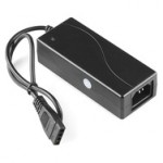
 Ok, so I smash the enclosure of the power supply that I ordered, unsolder the IEC C13 connector from the board, solder on some wires, connect them to the contraption, and measure: a bit more than 5V and a bit more than 12V with common ground. Great!
Next is connecting it to the Raspberry Pi. I cut the micro-USB chord, identify which wire is which, and solder the black and red strands to the power board. (Obviously after having disconnected the contraption from the outlet.) I plug the micro-USB connector in to the Raspberry Pi, plug in the contraption, and voila, the Raspberry Pi boots! Because it is already set up, I can ssh into it.
Now to the MOSFET stage that will convert 3.3V signals from the Raspberry Pi board to the 12V/125mA that the relays need. Here’s the circuit that I’m using (with apologies for the schematic, it’s the best I could do with OmniGraffle):
(For the professionals, I admit I used to know more about this when I was a teenager. But then, it works!) I put the 10kΩ resistor there to pull the MOSFET’s gate to zero, even if the GPIO pin is not configured, so the relay stays off. MOSFETs’ gates are so well insulated, a charge might stay there otherwise for a long time, and keep the relay on. (There is a great experiment carrying electrons to the gate of a MOSFET with your finger and switching it: that’s how little charge it loses on its own.) The diode is intended to short whatever funny self-inductive currents might be generated by the relay when it is switched off. I don’t know whether or not it will do this and can’t measure it because I don’t currently own an oscilloscope. It won’t hurt in any case. Note the diode is directed in the “wrong” direction so it never does anything if the relay behaves. The MOSFET I chose apparently already has a similar diode built-in that shorts to ground.
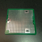
 To assemble two of these (I need to switch two pool pumps), I cut one of these little prototyping boards in half and assemble it there.
Next I hook up the transistor stages to the 12V output of the power supply and one of the relays. Touching the gate of the transistor with the 12V produces a clicking sound! Yes, the transistor is driving the relay. The next check is very important: if I keep it on, does the transistor get warm? If it did, that’d be bad news, but fortunately it behaves like the spec and switches cleanly without losing much power and getting warm. The relay and the power supply also stay cool.
One final step: instead of connecting the gate to power directly, let’s power up the Raspberry Pi, and connect it to one of the I/O pins. Using the same web access via piStatus.pl as described earlier, I can now switch a relay on and off over the web. And still nothing gets hot. This is where I take a break to celebrate, because everything else seems “merely work” from now: the basic approach has been proven.
Next post: Mechanical assembly


