As a proud new owner of a 3D printer, obviously I have been attempting to learn how create 3D CAD models for it. My friend Joe Andrieu pointed me to OpenSCAD, an open-source, “programmer’s” CAD tool. Unlike all other CAD tools I’ve ever heard of, OpenSCAD uses a textual programming language to describe the object you want to create, and gives you a viewer to see what you described. Yes, as a programmer, you feel right at home.
So in the hope that it will be useful to others, here’s what I learned from my first “real” attempt at design: a reasonably complex enclosure for a single-board computer and a disk:
- It’s useful to have good sketches on paper first.
- For an object that is supposed to be functional (as opposed to a work of art, where that might be different), there are many decisions to make made, such as whether some support comes from the bottom or from the side. You should try them out on paper first before trying to model them. It’s much faster that way.
- If you are a little shaky about vectors in 3D space, it is worthwhile reviewing that first. For example, to use OpenSCAD’s
mirror()function, you need to be able to define “the normal vector of [the mirror] plane intersecting the origin”. Unless you are certain what that means, OpenSCAD is going to be hard. - Decompose your design into parts and get those parts right first, one at a time. OpenSCAD has “modules” for that purpose. For example, I created a “Standoff” module, which is basically a cylinder with a hole in the middle. Once this did what it was supposed to, I could instantiate this Standoff everywhere in the design where I need one.
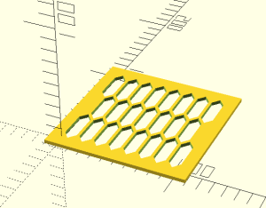
 It’s very nice that you can basically program to your heart’s delight. For example, I created a module for “VentilationHoles” that takes 4 parameters: the width and height of the area that is supposed to get the holes, and the numbers of rows and colums of holes to make in that area. My code can then lay that out. Wherever I like to have ventilation holes in my enclosure, I simply subtract that module from the wall. (You are wondering about the shape of these holes? They need to be 3D-printable, so better not make anything horizontal). Here’s the code that created this picture:
difference() { translate( [ -10, -10, 0 ] ) { cube( [ 120, 120, 3 ] ); } translate( 0, 0, -3 ) { linear_extrude( 9 ) { VentilationHoles( 100, 100, 3, 8 ); } } }- With manual sketches in hand, carefully pick where you are going to put the origin of your coordinate system. If you chose badly, you’ll have to carry around far too many terms into your calculations. In my case, the best place for the origin was on the bottom-left corner of my enclosure, on the inside of the wall.
- Don’t forget: walls have a non-zero thickness. Chances are that many other dimensions of your design are going to depend on the wall thickness.
- Your design is going to have some key dimensions. Some of which you can choose yourself (like: how tall should a box be), some you have been given (like: the places your thing needs to get screwed to some other thing) and some which are derived from the previous two. Be very careful in distinguishing between them, otherwise you’ll have a terrible time if you need to resize or move something half way into your project.
- OpenSCAD has two types of variables. Regular ones (like
foo), and “special” ones (like$foo). Define all your key parameters as special variables in your main model file. That way, you can access them from the entire model and don’t have to pass them into each module. This makes your like much simpler. - It helps to consistently name your variables because there will be lots of them, and it will be really easy to confuse them. Here’s the scheme I came up with:
- Name endings indicate what type of dimension it is:
_w(width),_d(depth),_h(height),_t(thickness, of a wall for example),_dx(distance along the X axis) etc. - Things are named in CamelCase, so for example,
centerStandoff_his the height of the center standoff. - When something refers to two things, they are separated by underscore. For example:
foo_bar_dxrefers to the distance betweenfooandbaralong the X axis.
- Name endings indicate what type of dimension it is:
- Finally, on the modeling itself: it was not obvious to me that if there are two mathematically equivalent ways of describing an object, OpenSCAD might have dramatically many problems with one of them, but not the other. (This is another reason for proceeding one step at a time.) In particular, never put object X next to object Y, and assume they will be joined, even in a
union(). They won’t, instead, due to numerical errors (probably) you will get an object that is not a 2-manifold (I think that’s the error message) and you much rather not debug this. - As soon as there is an “error” or “the design needs to be repaired”, step back, and do that. On my first print, I had relied on the Slicer’s confident assertion “6000-something errors repaired” and the print resembled the model in no way at all.
- While you might be thinking, this is all 3D, often it makes a lot of sense to model a part in 2D only (OpenSCAD has primitives for that as well), like on paper, and then to “extrude” it into the third dimension. In many cases, that’s the simplest approach, and my VentilationHoles module above, if you look closely, does exactly that: it does not have a Z dimension and so I don’t need to pass that around. It only gets that through the
linear_extrude( howFar ).  You should spend some time watching your printer print things you downloaded off the web, such as from Thingiverse.com. It will give you some appreciation about what’s “inside” an object, and just how your printer moves to create that object.
- To make a hole in something, you subtract one shape from another. Make sure the subtracting shape is wider, in both directions, than the object that you subtract from, otherwise you will run into the same numerical problems as when placing two objects right next to each other. In the code above, you can (probably) easily see that my cube with the holes is 3mm thick, but that my VentilationHoles are 9mm thick (so they “stick out” in either direction by 3mm).
- Finally, some things you will only find out by trial and error with your printer. For example, if you print a thin wall, and the thin wall touches something on the inside, that will be visibile from the outside! I did not expect that, but probably has something to do with different flow and cooling of the filament when other objects are around.
- I haven’t mentioned the tool chain. Somehow those Prusa guys never quite documented this clearly. This is how it goes:
- Create a 3D model, in a 3D modeling tool such as OpenSCAD, or FreeCAD or whatever.
- When done, export that model to a
.stlfile. This file contains the geometry as a long list of surface triangles (everything becomes a triangle). - The second tool is called a slicing engine, such as Slic3r. You import the
.stlfile. The slicing engine is responsible for emitting step-by-step instructions for the printer. So it needs to know about your printer and your printer vendor should have published their printer’s parameters somewhere. In Slic3r, you place your 3D model onto the (virtual) print surface of your printer, and then pick parameters such as the resolution at which you want to print. - When done, export the resulting
.gcodefile. (No, it has nothing to do with Google as the format is decades older, apparently.) This file contains instructions such as “move to coordinate such-and-such in a straight line” etc. Give that file to your printer, and start printing!
Ok, end brain dump. If I think of more, I’ll add it later.
Summary: it’s fun!

