Back in the days when I went to (the German equivalent of) high school, we had to write the famous “Facharbeit”: a thesis in the field of your specialization for which you had a whole year. I wrote about infrared remote controls and built a bunch of electronics — which was great fun, except that my physics teacher was completely out of his league attempting to evaluate it. (After all, it’s only first principles in physics that apply to electronics.) According to Wikipedia DE, it’s still part of the curriculum. But I digress.
Here’s an idea for a project that somebody motivated could do at this level — and perhaps as a junior-level thesis at college, in mechanical engineering, and that would be very useful to lots of other people with 3D printers:
Experiment with and document the tolerable stresses of various shapes of 3D-printed connectors.
 Here’s the problem:
- You print several parts on your 3D printer. Those parts need to be connected into a whole.
- For example, you might want to do that because you print different parts with different materials (e.g. colors). Or because the whole is too big for your 3D printer whose printing surfaces are typically quite small.
- How should you connect those parts, so that the likelihood or breakage is minimal?
I’m not a mechanical engineer, but my understanding is that there are big books in mechanical engineering that list the mechanical properties of lots of things, such as screws, bolts, and various connectors, parameterized with temperature, material and things like that.
It would tell you thing such as: if you take a bolt of type M4 made from stainless steel of type S, with tolerances T, the maximum force it can take is X Newton along its primary axis, but only Y Newton of shear (“across”) forces.
Imagine you design the Golden Gate Bridge. Would such a book be useful? You bet! In fact, I much rather not drive across your bridge unless you used a book like that quite diligently for every part of your bridge design!
Does such a book exist for 3D-printed parts? Not that I can tell. Certainly I have not seen it, or seen it referenced. So the point of the project would be to research what loads various 3D-printed connectors can take, and document them, and I guarantee that many hobbyists — and probably professionals — with a 3D printer would reference it for years to come.
Here is how I would go about it:
- Define a standard part that’s being cut into two with different shapes of cut. That standard part could be as simple as a flat cuboid, with a few strategically placed holes that would connect to the test rig.
- I would put some steel bolts through those holes, and using suitable cables, connect them to something solid on one side, and a force meter on the other. Which in turn would be connected to a spindle of some kind by which one can gradually increase the force.
- Now print a large number of test parts with various cuts, materials and thicknesses. For extra credit, vary temperatures and humidity.
- And pull until the connector breaks or otherwise comes loose.
- Test straight pull, and shear, and perhaps torsion.
- Document every experiment.
- Then, look at the result and derive some general relationships, such as:
- if you have a choice of one of three types of cut, use puzzle cuts with round edges for forces that primarily pull;
- use a wider base of the puzzle piece for loads that primarily shear;
- or whatever … I am making this up, because I don’t know what which shapes are better than others at what! And from what I can tell by looking at others’ designs, they don’t know either! So this is needed.
- Publish on the web. (and then use for college applications, or more likely, for job applications!)
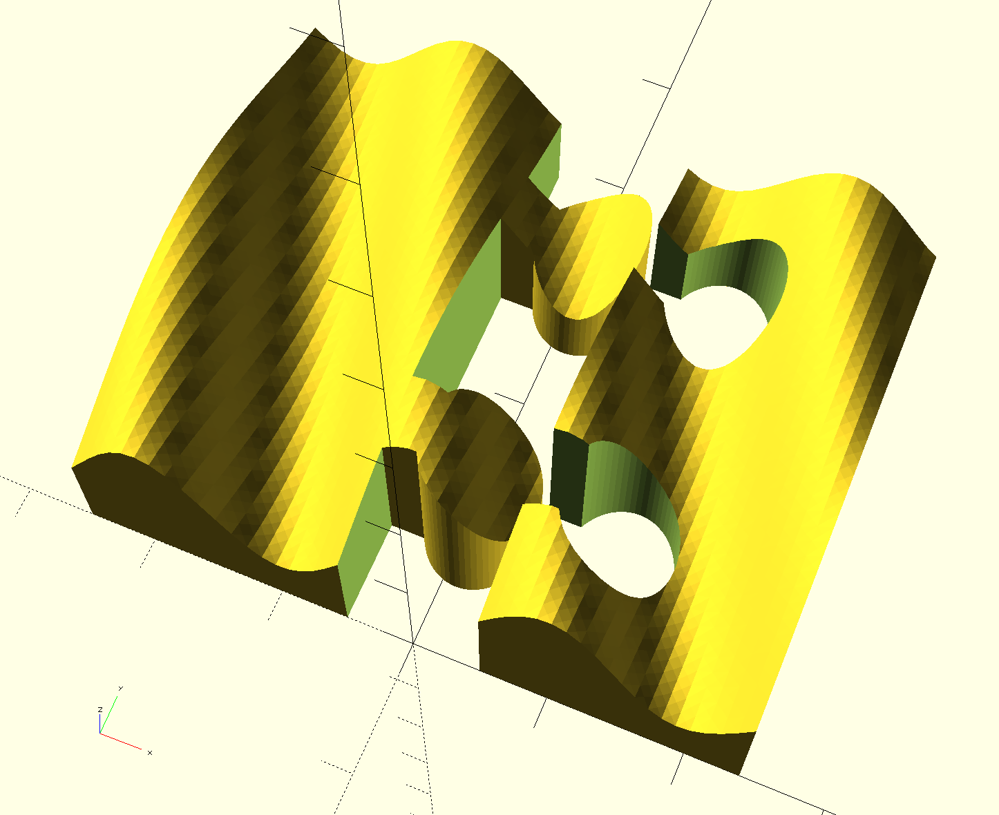
The thought occurred to me because I just created an OpenSCAD (a mechanical CAD tool often used for creating 3D-printable parts) library that lets you cut your parts in arbitrary shapes, and I’d love to know which shape of cut I should use for a part I’m working on, and I have no clue.
Oh, here’s the cut library: https://github.com/jernst/openscad-cuts. And the picture above is one of the cuts (a “puzzle cut”) that it knows how to create.
Comments
One response to “A cool research project for somebody aspiring with a 3D printer”
This is pretty cool; sounds definitely like it would be something for the engineer in all of us. I had an idea where I could 3D print a necklace I have in both gold and silver for all my friends, though haven’t the dangdest how to go about such a thing.